Tweaks
Tuning the Gain
In an op-amp circuit, the resistors in the feedback loop (R3 and R4 in this case) set the gain: the amount by which the output voltage is multiplied compared to the input voltage. The formula for gain in this amp is
![]()
To change the amp’s gain, you can change whichever of the two resistors is most convenient. You should pick values somewhere in the 1 kΩ to 100 kΩ range. Lower is better, for a couple of reasons. First, high values will increase your circuit’s suspectibility to stray RF and electromagnetic noise. Second, higher resistor values are inherently noiser. (You can explore this phenomenon with my op-amp noise calculator.) If you go much below 1 kΩ, the current wasted through the feedback loop will become significant.
The default gain of 11 is fine to start with. It won’t let you use the full sweep of the volume knob unless you have very inefficient headphones or a very weak source, but it does provide good, stable operation of the op-amp. As you lower the gain, you make it more and more likely that the op-amp will become unstable. Indeed, some op-amps won’t work reliably at low gains. The OPA13x series chips are “unity gain stable,” meaning that you can take them down to a gain of 1, if your circuit is built soundly. (You get a gain of 1 by connnecting the output straight to the inverting input.)
I have used a gain as low as 2 with inefficient Sennheiser 500 series and AKG K x01 headphones, when the source is strong enough. Similarly, a gain of 2 or 3 with efficient headphones should work fine even with weak sources. A gain of 5 or 6 is practical for almost all combinations of sources and headphones.
For your first amp, build it with a gain of 11 at first. Then once it’s working correctly, try out different feedback resistor values, checking carefully for audible distortions with each change. Once you get to a gain level you like and it’s stable, box it up.
Quieting Noises (R5)
Normally the R5 position in the CMoy amplifier is shorted. (0 Ω) This gives the amplifier the best control over the headphone drivers, and results in the best sound in most circumstances. Sometimes, however, putting some resistance in the R5 position is necessary to quiet some sort of noise you hear in the headphones.
Before I go into more details, please read all the information on noise in the companion article Basic Troubleshooting for Headphone Amplifiers. The solutions in that article, if they work, are superior. Adding R5 should only be done as a last resort.
Having tried everything else to get rid of noise, try putting 10 Ω to 100 Ω in the R5 position. Higher values will be more effective, but because lower values have fewer bad side effects, your incentive is to use the lowest value you can get away with.
Adding a DC Power Jack
Wall Power Only
The simplest solution is to wire up a standard DC power jack to the power supply. I like the barrel type connectors, since they’re the safest for this application. I’m a particular fan of the 5.5mm/2.5mm size, because it’s the sturdiest readily available type, and my favorite line of commercial audio-grade power supplies (Elpac’s WM series) uses this connector style. My second choice would be the 5.5mm/2.1mm style, which is similar but with a smaller center pin.
Batteries Plus Wall Power: Easy Method
The main problem you have to solve if you want to run your amp from both batteries and a wall supply is how to prevent the wall supply from trying to charge the batteries. Regardless of whether you use alkalines or rechargeables, simply connecting a wall supply across them will kill them.
The easiest way to solve this problem is to use a “closed circuit” DC power jack. These add a switch and a second circuit to a regular power jack. This second circuit is normally closed; thus the name. When you stick the DC power plug into the jack, the second circuit opens. If you connect the batteries through the second circuit, they get cut out of the circuit when you plug the wall supply in. I show how to wire a closed-circuit DC power jack in the companion article, How to Wire Panel Components.
Unfortunately, the switch inside some closed-circuit jacks is rather delicate. The DC power plug can snag on the switch while you’re inserting it and bend it. If you’re lucky, you’ll just bend the switch contact a little bit, so that you can bend it back with a small screwdriver. If you’re unlucky or ham-handed, you’ll bend the switch contact completely out of shape and be forced to replace the jack. To some extent, you can solve this problem by paying particular attention to the DC power plugs you use: the better kind for this application have chamfered leading edges, so they’re less likely to snag than the blunt kind. The high road is to avoid closed circuit jacks if you don’t absolutely have to use them.
Batteries Plus Wall Power: Clever Method
It’s possible to have our cake and eat it, too. We can use a plain, switchless DC power jack and still have both battery and wall power. The easiest way to do this is to use a diode OR bridge:
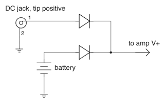
Diode OR Bridge
The name comes from the fact that it allows only one power source or the other to run the circuit, never both at the same time. This prevents the wall supply from trying to charge the battery when both are connected.
The diodes can be any generic type, such as the common 1N4001. The bar on the diode symbol in the schematic represents the diode’s cathode, and the corresponding terminal on the physical diode is marked with a stripe. So to build this circuit, you simply connect the two cathodes together with the V+ line to the amplifier, connect the positive side of each power source to one of the other diode legs (the anodes), and the negative side of each power supply to V- in the CMoy amp.
There are a few restrictions with this method. First, because a typical diode has a forward voltage drop of around 0.7 V (the “diode drop”), this can prevent you from getting the full use out of your batteries. (Whether this is the case depends on matters discussed in the companion article, Op-Amp Working Voltage Considerations.) The second restriction is that the wall power supply must be at least one diode drop higher than the voltage of a full battery, or else it will not reliably cut out the battery. Beware that fresh alkaline batteries have a higher terminal voltage than they are rated for; a fresh “9 V” battery actually measures more like 9.6 V, for instance. Rechargeables similarly have higher terminal voltages than their nominal voltage when fresh out of the charger.
The way the diode OR bridge works is actually quite simple. A diode only conducts current when its anode (positive) voltage is at least one diode drop above its cathode (negative) voltage. Since the cathodes are tied together, connecting the wall supply pulls the common cathode up so it’s less than a diode drop below the battery voltage, so only the wall side diode conducts. (In practice, you usually overdesign it so the common cathode is actually higher than the battery voltage.) When the wall supply is removed, the common cathode point falls back down to one diode drop below the battery voltage, so the circuit still gets power.
Let’s work a concrete example. We have 2×9 V for our battery supply, which we’ll conservatively estimate at 19.2 V when fresh. We’ll use standard 1N4001 silicon diodes, which have a diode drop of 0.7 V at the low currents you’ll see with a CMoy amp. And finally, we’ll use a 24 V wall power supply. So, with only the batteries connected, the common cathode point is 0.7 V less than 19.2 V, or 18.5 V. When we connect the wall supply, the wall side anode goes to 24 V, which raises the common cathode to 23.3 V. The battery can never run the circuit while the wall supply is connected, because the battery side anode is always at least 4.8 V lower than it has to be for the battery side diode to conduct.
Picking a DC Wall Power Supply
If you do the above tweak, you’ll need a DC power supply of some sort. (As opposed to an AC power supply. Powering a CMoy with AC will fry it right quick!)
The most important feature to look for in the power supply is isolation. This means that there is no direct connection between the AC side of the power supply and the DC side, which is necessary for the CMoy’s virtual ground circuit to work properly in many common situations. You can test whether a supply is isolated by using an ohmmeter to test for conductivity between all combinations of input and output pins on the supply; it’s most common in non-isolated supplies for the V- output to be tied to either earth ground or AC neutral on the AC input side of the supply. All linear-regulated and unregulated supplies are isolated. The other main type of supply is switching-regulated, which are often not isolated. If you’re not sure whether a particular power supply is isolated and can’t test it, assume that it isn’t.
The next most important spec is whether it’s regulated or not. You can count on an unregulated supply to put a lot of noise on the amp’s power rails, which may get through to the output in audible amounts. (See my article Op-Amp Power Supply Quality Considerations for further details.) Regulation fixes this problem. The two most common types of regulation are linear and switch-mode.
Switch-mode regulation also puts out a fair bit of noise, though of a different type than you get from an unregulated supply. Whether or not this is audible is a complicated issue. See the above-linked article for more discussion on this topic.
Linear-regulated power supplies are best for high-performance audio. Unfortunately, there aren’t that many commercial linears suitable for audio DIY on the market. I discuss many alternatives in a companion article, Where Can I Get a Wall Power Supply for My Amp?
The amount of current your supply can put out really doesn’t matter for this application — even the crummiest little wall wart can supply 100 mA, whereas your CMoy amp shouldn’t ever draw more than about 20 mA.
Using Different Caps
There are two main numbers that describe a capacitor: its voltage rating and a measure of how much energy it can hold, given in fractions of a farad. (One farad is a very large amount of capacitance.)
Voltage Rating
The voltage rating simply tells you how many volts the cap will tolerate. You should use a cap with a rating that’s greater than the largest voltage you expect it to see. However, higher voltage ratings mean physically larger cases and higher cost; there are no secondary performance benefits from using caps with a higher voltage tolerance than necessary. Consider the power caps: if we’re using a 2×9 V battery supply (18 V), a 16 V capacitor in the power supply would be insufficient, a 25 V cap would be fine, and a 35 V cap wasteful.
You might think you could actually get away with a 10 V cap for our example, because the virtual ground divider is supposed to divide the power supply voltage by 2, putting only 9 V across each power supply cap. The first problem with this logic is that the divider in the CMoy will be imbalanced in actual use. If you to use 10 V power supply caps with our 18 V example power supply, it’s very likely that one of the two caps will see more than 10 V and be damaged. The second problem stems from the fact that you should never optimize something like voltage tolerance assuming that the circuit is working properly. Let’s say you’re using 10 V caps with a 15 V power supply instead. In this case, it’s quite unlikely that you will get more than 10V across one side of the supply in normal operation. But, what happens if something goes wrong? There are several ways the virtual ground divider could fail, putting all 15 V across one side of the power supply. Bye-bye power cap.
Bottom line, it’s prudent to make your power supply caps’ voltage tolerance at least equal to your rail-to-rail power supply voltage in this amp.
Capacitance Rating
The caps’ values will change the way the amp performs. For the power caps, 220 µF is adequate, but bigger ones will provide a bigger current reserve, which can be useful in handling high instantaneous loads, like big drum hits. I’ve tried 470 µF caps in my CMoy amps before, and it does improve the bass handling significantly and they’re not all that much bigger than 220s.
As for the input caps (C2), a larger cap will improve bass handling, but it’s by a different mechanism than with larger power caps. See the companion article, Input Capacitors for Headphone Amps for a full discussion. Bottom line, the default 0.1 µF is a bit on the low side. Try 0.22 µF, 0.47 µF, or even 1.0 µF instead.
With film caps, the smallest voltage tolerance you’ll likely be able to find is 50 V. Although even 50 V is way too high, don’t worry about it: just get the lowest-voltage caps you can find. If you go with polypropylene caps, you probably can’t find caps with less than 200 V tolerance. If that’s the lowest voltage tolerance you can find, go ahead and use them. Just don’t think that getting the 800 V versions will do anything more than waste board space and money.
Capacitor Type and Quality
There are many types of capacitors, because we have so many reasons for using capacitors. No single capacitor type works for all situations.
For the CMoy power supply, electrolytics are the best choice. Only they have the high capacitance values and low cost needed for this task. Different brands of capacitors can sound different. Many companies make good electrolytics: Panasonic, Nichicon, ELNA, Rubycon, Sanyo...
Electrolytics do have a downside, which is that their value tolerance is very bad, and they have high distortion. Neither problem matters in a power supply, but it would be foolish to use these for a CMoy’s input caps (C2). For this job, plastic film caps are best. Good brands are Panasonic, Vishay, Wima...
Not all capacitor lines from the above listed companies are equal. Do some searching online for advice if you want to use different capacitors than the one I recommend in the parts lists. There is some related advice in the companion article, Input Capacitors for Headphone Amps.
Before you go deviating from caps recommended to you, especially if you’re swapping them into an existing layout, check their datasheet to see how large they are. If you’re staying with the same product line and just getting a different value, the replacement could be larger in diameter, or height, or both. Or, you might get lucky and find another cap in the same line that’s the same size as the one it’s replacing. (It happens!) If you’re switching to a different manufacturer or product line, it’s doubly important to check the datasheet because it’s common for a higher quality cap to be larger than a lower quality cap, all else being equal.
Tweaking the LED Resistor
The RLED resistor is there to limit the current going through the LED. If you don’t limit the current, the LED will burn itself up. (Yes, they actually get a bit hot to the touch before they stop glowing. If you have a spare LED and want to see what happens, just touch the leads to a 9 V battery’s terminals.)
The formula governing current through the LED is:
![]()
Or, we can rearrange that to calculate the proper resistor value, given the current we want:
![]()
These equations might look a little funky at first, but they’re actually very simple. Let’s say we’re using a 2 V green LED; that’s Vf, the “forward voltage drop.” We’ll use an 18V power supply; that’s Vs, the “supply voltage”. We’ll stick with the default value for RLED here, 10 kΩ. We’re calculating the forward current through the LED, I. The top part of each equation subtracts the LED’s forward voltage drop from the supply voltage, which gives the voltage across RLED. So in this example, 2 of the 18 supply volts is dropped across the LED, leaving 16 V across the RLED resistor. After that, it’s just Ohm’s law: I=V÷R. This tells us that the current through the LED will be 1.6 mA if we use the standard RLED value of 10 kΩ. The second equation is just another rearrangement of Ohm’s Law: R=V÷I.
LED brightness is proportional to the current going through it. Common LEDs can handle at least 20 mA, but you only need 1 to 2 mA for efficient red, green and amber LEDs to seem adequately bright. So for our example green LED, 1.6 mA will be fine. Even with a piggy blue or white LED, I never need more than 5 mA to get adequate brightness.
In this circuit, the LED voltage and the RLED value are constant. So if you look at the first equation, current can only vary if the supply voltage varies. This will happen with battery power supplies. Taking our example above a step further, what if our “18 V” power supply is actually 2×9 V in series? In that case, the battery voltage will drop to about 10 V by the time the batteries are dead. Now there will only be 0.8 mA going through the LED. From the “1 to 2 mA” advice given above, you’d be correct in saying that 10 kΩ is a little high for RLED in this situation. Dropping it to 7.5 kΩ or even 4.7 kΩ would help.
Beware that you’re trading battery life for LED brightness here. You might decide that you can tolerate a dim power LED when the batteries are nearly dead in order to squeeze a bit more run time out of them. I find that efficient LEDs reach minimum useful brightness with about 0.2 mA. Let’s use the second equation, with our minimum supply voltage of 10 V, our 2 V green LED, and our 0.2 mA minimum current target. We find that RLED should be no more than 40 kΩ to get minimum brightness at minimum battery voltage. We might choose 33 kΩ as a compromise, then, between getting reasonable brightness and getting absolute maximum battery life.
Improving the Virtual Ground Circuit
In the standard CMoy power supply, the two 4.7 kΩ resistors create a “virtual ground.” This circuit works adequately in many situations, but it has weaknesses. See the full discussion in this article, which also shows improved virtual ground circuits.
This space intentionally left blank. :)