Tweaks
Building for Tweakability
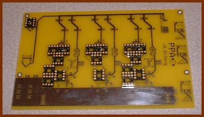
Virtually every hole in the board is on 0.100" spacing relative to all the related holes. Also, each resistor's holes are 0.300" apart. This means you can use socket strips and header pin strips in the board. If you did this for everything where it makes sense, you would in effect have a PPA breadboard for maximum tweakability. :) Here's a list of all the places you can do this and ideas for why you might want to do each one:
- Resistor/diode blocks — Use SIP socket strips
to allow easy swapping of resistors and diodes. There are about
80 pads you can fill this way, so you might stop and consider
which parts you're likely to be changing before plopping sockets
all over the board.
- Power input — V+, B+ and V- are set up to
allow you to put a Molex KK style connector on the board in
one of two positions. This would let you disconnect the power
jack from the board, or the battery board from the PPA board,
depending on how you have the power flow set up.
- Power switch — I'm not sure what connector would
fit here, but probably something could be worked out. A 2-pin
Molex KK can be made to work for just one of S1+ or S1-, but a
small foursquare connector would work better, if you can find one.
- Signal input — Like with the power input, you could put a Molex KK connector here. There's more space here, so almost any connector with 100 mil pin spacing would work here, actually. Between this and the previous tweaks, you could completely separate the amp board from the rear panel, without desoldering anything.
|
A PPA v0.012eng "Breadboard"
Paralleling Buffers
The PPA board will accept one to four buffers per output channel. Paralleling buffers has several benefits:
- It improves the slew rate of the buffers, which lowers
distortion. This helps the treble the most.
- It increases the transient output current ability of the
amp. Typical headphones don't need more continuous current than
one buffer can supply, but additional buffers can help deal with
transients that can indeed tax a single buffer's capability. Bass
response benefits the most from this.
- It lowers the output impedance of the amplifer. Most headphones sound best when the amplifier's output impedance is as close to 0 as possible.
You don't need to parallel buffers to get good sound. Just one per channel still sounds pretty darn good. Sticking with one buffer per channel is reasonable if you want to save money or reduce current draw when running from batteries.
One reason the '5002 buffers sound so good is that they don't have output protection. Output protection circuitry means that it's harder to kill the chip when shorting the output, but it also interferes with sonic quality. The '5002 buffers will put out as much current as the load will accept, even if this destroys the buffer in the process. When driving headphones to normal volume levels, this isn't a problem because the headphones' impedance limits current through the circuit. But, examine a headphone jack and plug: you'll find that the plug shorts the outputs to ground momentarily as you pull the plug out. If you pull the plug out slowly enough or the amp's output voltage is high enough, this momentary 0 Ω short can make the buffers put out enough current to kill them.
|
Be kind to your buffers
You can ameliorate this risk by adding output buffers. The more buffers you use, the harder it is to kill the buffers because there are more buffers to share the load. While you can kill any number of buffers if you try hard enough, having more buffers does give them a better chance of surviving if something bad happens to the amp.
Changing the number of ground channel buffers does not change the distortion results. Therefore, it's reasonable to have buffer counts like 2-1-2, 3-1-3, 3-2-3, etc. However, skimping on ground channel buffers is likely to impact the amp's ability to survive shorted outputs. X-X-X buffer configurations will be the best choice for most amps. X-Y-X only makes sense when you're trying for some kind of balance between sound quality and battery life, and you're willing to sacrifice safety to get the best balance between those two.
Theoretically, making the number of ground channel buffers equal to the total number of output channel buffers is the safest. (1-2-1 or 2-4-2.) If the output channels' signals are in phase, the ground channel sees twice the load of each output channel, so having 2× the number of buffers on the ground channel as on each output channel makes some sense. However, this is really an edge case. What happens in practice with headphones is that either the current sunk by the ground channel is well within 1 buffer's capability, or there's a dead short from just one channel to ground so 2-2-2 is just as safe as 2-4-2. 2-4-2 would make sense if you were somehow able to short both channels to ground at once, but that doesn't happen with headphone plugs. It might also be helpful if you were making the amp power low-impedance speakers, since the amp will survive as you turn the volume up until you finally exceed the amp's current handling ability. Since the PPA isn't meant to power speakers, this case is also academic. It might make sense for uncommonly difficult to drive headphones like Sony F-1s or AKG K-1000s, though.
Remember to add the corresponding buffer input resistor when adding each buffer.
Buffer Rolling
Just as you can "roll" op-amps — that is, swap different op-amps in to change the sound — you can roll buffers in the PPA. The standard buffer for the PPA is the Intersil HA3-5002-5, but the Intersil HA3-5033-5 and the Burr-Brown OPA633 also work in the same sockets. They are equivalent parts from different sources. They work without problems in the v1.1 boards, but there's a workaround required if you want to use them in the v1.0 boards. These alternate monolithic buffers have a much higher quiescent current and a lower output current ability than the 5002, which is why they're not the preferred buffer for the PPA. However, if you want a more laid-back sound than you get with the 5002, these buffers can provide that.
A recent development is buffers made from discrete parts, such as Uncle Phil's Discrete Diamond Buffer Triad Module and Glassman's diamond buffer. These designs are both different from each other and different from the monolithic buffers, so they give different sound.
Biasing the Op-Amps into Class A
"Class A" refers to configuring an amplifier so that its output devices remain turned on all the time. This reduces thermal variation and eliminates crossover distortion, which makes the amp sound better. You can bias the op-amps in the PPA by adding the cascode JFETs and the source resistor.
Before I get into the PPA-specific details, you should read my article Biasing Op-Amps into Class A. Q1 and Q2 in the article are the same as Q1 and Q2 in the PPA, and Rs corresponds to R8 in PPA v1.0 and R9 in PPA v1.1.
We made setting up the cascode much easier in PPA v1.1 by changing R8 into a trim pot, now called R9. You simply solder all the parts down, then power the amp up and measure the voltage drop across R10. If R10 is 1 kΩ, then each volt of drop across R10 equals one milliamp through the cascode, so it's easy to trim R9 to get a particular op-amp bias current. 1mA is a good starting value, but you should try other values to see if you can hear an improvment in the sound at different bias levels.
Adding Crossfeed
There are three holes near the rear edge of the circuit board. These are for mounting version 1.1 of my modified Linkwitz crossfeed PCBs on the board. You only use two of the holes, the middle one and one outside one, depending on where you want the PCB to be positioned over the amp board. See the previous link for more information.
Adding Bass-Boost
In cooperation with the op-amp, R7 and C7 in the PPA form a type of "shelving filter", raising the output level of low frequencies: in other words, it boosts the bass. The advantage of this type of filter over other circuits is that it is completely bypassable and it works in conjunction with the op-amp circuit which had to be there anyway so it only adds two components.
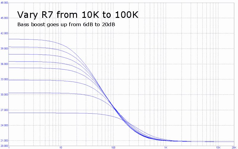
R7 raises the level of the highest bass boost:
|
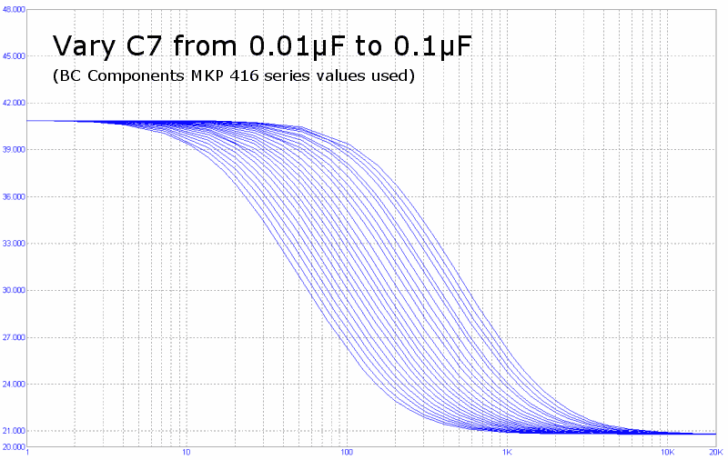
C7 changes the point where the bass boost begins:
|
The larger the value of C7, the lower the frequency where boosting starts.
Notice how finely spaced the lines are on the graph. This is a log-log scale graph, though, so in reality the jumps in corner frequency between two close capacitor values get larger as the capacitor gets larger. Therefore, if you want the bass boost to extend clear up into the low midrange, you must use a line of capacitors with fine-grained steps between values or else suffer from large jumps in the point where the boosting begins. That's why we like the BC 416 line for this purpose. In most cap lines, there's nothing between 0.047 µF and 0.1 µF. In a few, there's an 0.068 µF in between, but that's still not very good. The BC 416 line also has 0.075 µF, 0.082 µF and 0.091 µF in this range, which helps a lot when it comes to fine-tuning the bass boost behavior.
The value of R4 also has a small effect on the behavior of the bass boost circuit:
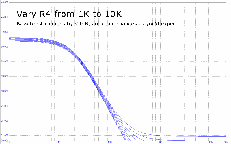
|
I include this graph only to show that you can vary R4 without worrying about what it will do to the bass boost behavior.
It's important to realize that this circuit doesn't roll off at DC, so any DC offset on your amp's output will also be boosted when you engage the bass boost. It is important that you minimize DC offsets in the amp before adding bass-boost. A 20 dB boost (10×) can transform a harmless 10mV DC offset into a headphone-frying 100mV offset!
If you want to explore these issues in more detail before you turn on the soldering iron, I suggest you download a copy of the Micro-Cap 7 demo. Here is a circuit file for you to start with. (This is the circuit file I used when generating the above graphs, so it should be set up properly already.)
You can get some of the information you would get from the simulator without as much work by using the bass boost calculators.
If you're curious as to how this circuit works, look at R7 and C7 as two separate paths through the feedback loop. C7's impedance ranges from infinite at DC down to 0 Ω at high frequencies. Since 0 Ω in parallel with R7 is 0 Ω, at high frequencies the amp gain follows the standard formula, given as [1] below. (Yes, the gain formula is different in the Jung multiloop configuration, but this approximation suffices for our purposes here.) At low frequencies, C7's impedance is very high, so R7's resistance dominates the total impedance; it simply adds to R4's resistance, giving formula [2]. Between these two levels where the impedance of C7 is near R7's resistance, you have the slope you see in the graphs above. Formula [3] is derived from these two, telling you the amount of bass boost relative to the amp's normal gain.
	(R4 / R3) + 1                 [1]
	((R4 + R7) / R3) + 1          [2]
	(R7 / (R3 + R4)) + 1          [3]
Tweaking the Isolation JFETs
The standard Q3 configuration works well, but there's some room for tweaking here.
As I mentioned elsewhere, you can get up to about 30dB of isolation without really thinking about it. You can get better isolation by picking your Q3s such that the current draw of the circuitry "below" them is a high percentage of their IDSS. Because the IDSS of JFETs varies so wildly, you must measure your JFETs' IDSSes and use similar JFETs in all of the positions to get the best performance.
There are two consequences of doing this tweak. One, it makes rolling op-amps more difficult: you may have to change the Q3s at the same time to make the new op-amp work. Two, the voltage drop across a JFET increases the closer you get to its IDSS. This could be a problem for you if it drops too much voltage for your application, or it could be a way for you to use low-voltage op-amps while still using a high supply voltage for the buffers.
You may have noticed that you can jumper across all of the Q3 positions to get a single set of power rails for everything. It's my opinion that if you're trying so hard to save money that the cost of a few JFETs matters, you would probably be better off building an amp with an inherently less expensive design like the PIMETA.
This space intentionally left blank. :)