Op-Amp Working Voltage Considerations
There are many variables involved in picking the proper power supply voltage for your op-amp in order to power a given set of headphones. This article will give you the tools you need to decide on that number.
Calculating the Minimum Working Voltage
The first thing you have to find out is the minimum voltage you need to give the op-amp to get it to operate properly in your setup.
Headphone Voltage Requirements
Different headphones require different voltage levels to sound loud. You often see people talking about this in terms of headphone specs like impedance and sensitivity, but if you start from the specs you can only make a guess at the proper voltage level. If you want to know precisely how many volts your headphones require to sound loud to you, you’ll have to measure this value.
First, plug your headphones into a system that can drive your headphones as loud as you’d ever care to listen. The sound quality of the source doesn’t matter much, as long as it can drive the headphones loudly without clipping. Set the volume level to the loudest level you’d ever care to listen. This works best with a disc you find yourself always wanting to turn up the volume on relative to your other music; it could be because you like to rock out to that disc a lot, or that it’s mastered quietly and you like to bring the levels up a bit.
Then, unplug the headphones and play a 1 kHz or so full-scale (“0 dB”) test tone through the system. Most test CDs will have a test tone like this on them. If you don’t have a CD with this type of tone on it, you can find software that will let you generate the necessary WAV or AIFF files. Then use audio CD mastering software (e.g. iTunes) to burn those tracks to a CD-R.
Take your AC voltmeter and measure the voltage at the headphone jack between ground and either the left or right channel; you should get a value somewhere in the 0.25 V to 6 V range for typical headphones. This will give you the root mean square (RMS) AC voltage for the highest volume setting you’ll ever use with those headphones. (You don’t have to have an RMS voltmeter to get an RMS value when you’re measuring pure sine waves.)
RMS values are a kind of average that depend on the shape of the wave form. With a sine wave, the peak-to-peak voltage level (Vp-p) is actually 2.828 times higher than the RMS value. That is, the distance from peak to peak on a 1 VRMS AC signal is the same as 2.828 Vp-p. Since it’s these peaks you’re worried about when it comes to figuring out the op-amp’s working voltage, multiply the AC RMS voltage you measured previously by 2.828.
Op-Amp Output Limitations
An op-amp can’t put out more voltage than you give it. Most op-amps’ output levels are significantly lower than the voltage difference between the supply rails. Your op-amp’s datasheet will talk about this in the main data table, usually on the second or third page. It will give numbers for output voltage limitations at one or more power supply levels. If you’re very lucky, there will be graphs later on in the datasheet showing how maximum output voltage varies with power supply voltage and/or load. A typical op-amp has an output voltage limit somewhere in the ±1 V to ±3 V range. Often the output is more limited towards one power rail than the other — it might be +2.7 V and -2.9 V, for example.
Take the higher absolute value (2.9 V in the previous example), multiply it by 2, and add it to the peak-to-peak headphone working voltage value you calculated earlier. This is your minimum power supply voltage.
Raising the Minimum
Some op-amps will function at a given voltage, but they won’t sound their best until you raise the voltage from that point. If your headphones need less voltage than the op-amp needs to sound its best, you may have to raise the minimum voltage you mesaured above. This is very much op-amp specific; many chips don’t change in sound character much at all as you raise the supply voltage, once you’ve passed the mimumum working voltage level for your headphones.
A related consideration is op-amp load: most chips require more voltage when driving headphones or other difficult loads directly than when driving a high-impedance stage like a buffer or another amplifier. A chip that works fine at ±5 V in your preamp (10 kΩ load or better) might require ±12 V to work well when driving headphones (30 to 300 Ω load, typically).
You might not know how your chip behaves as voltage rises. Sometimes you can glean this information from the datasheet, sometimes you can search around on the Internet for lore regarding the chip, and sometimes you may just have to try it and see.
Deciding on a Maximum Voltage
Now that you’ve figured out the minimum working voltage, you now need to take into account the things that put a cap on the maximum practical voltage for your setup.
Op-Amp Supply Limit
All op-amps have recommended maximum operating voltages and absolute maximum operating voltages. You shouldn’t exceed the former, and you must never exceed the latter. Don’t guess on this, read the datasheet.
Capacitance Volume vs. Voltage
For a given physical capacitor size, higher voltage tolerances mean lower capacitances. For example, in the Panasonic FC series of electrolytic capcitors, the 1500 µF/10 V and 1000 µF/16 V parts have the same case size.
The point is, decide what the maximum diameter and height your rail capacitors can be, and then figure out what capacitances you can get at various supply voltages. You may decide that it’s best to use a lower supply voltage to get a higher capacitance. Notice that this is in direct conflict with the items above on minimum working voltage. You’ll have to strike some kind of balance here.
Power Rail Setup
It is typical with op-amp designs to have a dual power supply and to put the power supply capacitors between ground and one of the power rails. If your power supply is ±15 V, it is safe to use 16 V capacitors as long as the two supply voltages are truly independent.
Now, if you’ve got a single supply and you’re splitting it with a virtual ground scheme like in the CMoy pocket amp or the META42, this is not safe. There’s a risk that the virtual ground could “collapse,” putting the entire supply voltage across one rail of capacitors. Let’s say you’ve got a 30 V supply being split into ±15 V by some kind of virtual ground scheme, and you’re using 16 V capacitors. As long as the virtual ground rail stays precisely between the real supply rails, this setup will work fine. But what happens if virtual ground is shorted to one of the power rails? That would make the rails 0 V, 0 V and +30 V, instead of -15 V, 0 V and +15 V. The 16 V capacitors on the +30 V side could easily be destroyed by even a brief short like this. And, this is just one of a few different scenarios I can think of to make the virtual ground collapse. Bottom line, you should use power caps rated for at least as much as the total power supply voltage to be safe in a virtual ground based amp. If you take the safe route, it will be very difficult to pop your power caps by accident.
As regards the op-amp power supply, the point of this section is that a higher supply voltage for the op-amp may make it sound better, but it will probably require that you use less rail capacitance, which may make the amplifier as a whole sound worse. Let’s say you have an op-amp that works best at ±15 V. If you go to the expense and trouble of a dual supply, you can use 16 V capacitors. If you decided instead to go with a single supply split with a virtual ground setup, you’d have to use 35 V capacitors since you’d be using a 30 V single supply to get your ±15 V virtual dual supply. In this case, it might be better to compromise a bit on supply voltage to the op-amp by going with a 24 V supply so you can use higher-capacitance 25 V parts.
Picking the Power Supply Setup
Now that you have maximum and minimum working voltages for your amplifier, you can [finally!] configure your power supply.
Battery Power?...
If you’re using non-rechargeable batteries, they usually start off a little higher than their rated voltage; a typical AA cell starts off a bit over 1.6 V. They call it a 1.5 V cell because that’s the minimum voltage they guarantee for the cell within its advertised shelf life. An alkaline battery’s voltage drops slowly but steadily while on the shelf. When you start to use it, it drops in voltage faster but still steadily up to about 30 mA. Beyond that point, they start dropping in voltage nonlinearly with respect to time. You shouldn’t go beyond about 40 mA per group of alkaline cells in series.
NiMH rechargeables behave differently. When fully charged, they also give a higher voltage than they’re rated for: a “1.2 V” AA size NiMH cell might give 1.35 V when fully charged. But unlike alkalines, NiMH cells drop rapidly to just above their rated voltage and drop only slowly in voltage through most of their working life. By the time a NiMH cell is nearly depleted, it’s still up above 1.0 V. The discharge curve looks like this:
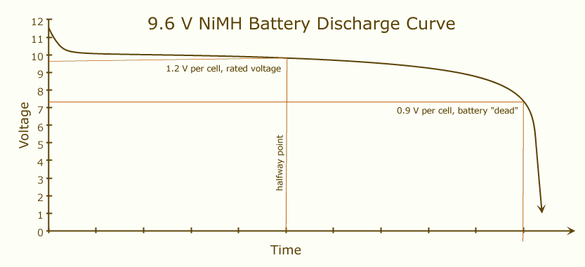
Notice that in this middle region, where roughly 90% of the battery’s useful power is, the discharge curve is nearly flat. This continues as long as the current drawn isn’t too high.
The maximum current you can draw from any battery is a function of cell size, and as cells get larger, NiMH cells perform proportionately better than alkalines. With the tiny cells packed into 9 V style batteries, NiMH has an ESR about ½ that of an alkaline. This means that for a given constant current draw, the voltage droop on a NiMH will be about half that of an alkaline. With a varying current draw, the ripple caused by the NiMH will be half that of an alkaline instead. When you move up to AAA cells, NiMH ESR is about ¼ that of an alkaline. By the time you get up to D size cells, NiMH’s advantage increases to about ⅒ the ESR of the same size alkaline cell.
To use the battery most efficiently, you need to calculate the size of your battery pack based on the minimum working voltage for each cell. For alkalines, each 1.5 V cell will go down to 0.9 V or so. “9 V” alkaline batteries are made of six 1.5 V cells, so their minimum working voltage is about 5 V.
NiMH 9 V style rechargeables are a more complicated story. Because of the nonlinear discharge curve, where you choose to call the battery “dead” is a bit more subjective. The same 0.9 V value used for alkalines is reasonable, but because the cell voltage is dropping so fast by the time it passes 1.0 V per cell, some people use that value instead. Also, NiMH “9 V” batteries come in 6, 7, and 8-cell varieties, with 7.2 V, 8.4 V, and 9.6 V nominal terminal voltages. You could therefore reasonably decide an 8-cell NiMH “9 V” battery is dead at 8 V, since there isn’t a lot of useful power left at that point.
It may be that you calculate that you need more batteries than is practical in your situation. Perhaps the enclosure you want to use doesn’t have room for a battery pack that large, or perhaps the fresh pack voltage is higher than your op-amp can handle, or perhaps you want to use some low-voltage power supply capacitors. No matter the reason, you can still use fewer cells than you calculated as long as you exceed your minimum working voltage; you just won’t be able to use your batteries fully. For example, you may have an enclosure that only has room for a single 9 V battery and your headphone and op-amp combo requires 8 V before it starts clipping on loud music. A single alkaline 9 V battery will work, but you’ll lose out on the capacity between 5 V and 8 V. This is inefficient, but sometimes you have no choice.
...Or Wall Power?
If you’re using a wall wart (AC to DC adapter), plug it in and measure its output voltage. Many wall warts will put out considerably more than their rated voltage when lightly loaded. Most wall warts are capable of at least a few hundred milliamps, but even a super-hungry op-amp based headphone amp won’t draw more than about 100 mA and typical ones are down below 30 mA. I have a wall wart here rated for 12 V at 200 mA that puts out 17.5 V when unloaded and 16.6 V when powering a META42 that draws about 11 mA at idle. You must account for this extra voltage when planning your amplifier.
Another good reason to measure the power supply is to make sure you have the polarity of your power jack wired correctly.
A Worked Example
This is all fairly complex, so let’s work through an example.
Let’s say you measure your headphones, and they require 3.75 VRMS to reach maximum volume. That’s 10.6 Vp-p. Then let’s say you’re using the AD843 op-amp, whose datasheet says that at ±15 V supply (i.e. 30 V), it can put out +11.5 V to -12.6 V. This means the output is limited to within +3.5 V and -2.4 V of the power rails. Being conservative, we take the higher absolute value and multiply it by 2, giving a 7 V limitation between the power supply level and the maximum output level. Adding this to our headphone supply requirements, we get 17.6 V. Let’s round it up a smidge to 18 V and call that our minimum working voltage.
The closest common power capacitor voltage tolerance to this is 16 V. That’s too low to be safe in this example, so as a first guess, we will go with the next common step up from there, 25 V.
Now let’s say we want to use AA size alkaline batteries to power the amp. To hit 18 V when each cell in the battery pack is nearly exhausted (1.0 V), you’d need 18 cells in series. This will give as much as 29 V when all the batteries are fresh (1.6 V+ each). This is dangerously high for our 25 V tolerance power supply capacitors — it will work correctly as long as the virtual ground stays centered between the power rails, but to be conservative let’s go up to the next common level above 29 V, being 35 V.
Now let’s modify the example: maybe we decide we’d like to use NiMH rechargeables instead. Since they stay near 1.2 V for most of their service life, we might be able to get away with 15 cells in series (18 V exactly), and 16 AA’s (19.2 V) would probably work quite well for our setup. Since each battery will probably give 1.4 V or so initially, our maximum starting voltage is under 23 V. So, we can bring our power capacitor tolerance down to 25 V tolerance safely in this situation, which may let us use significantly higher capacitance parts.
Let’s modify the example one more time. Maybe now we want to add a DC power jack that cuts the batteries out when the wall wart is plugged into the amp. Our minimum working voltage is 18 V, so we order a “regulated” 18 V supply, thinking that it will put out exactly 18 V. But oops, when it comes in we find out that it isn’t particularly well regulated, and it actually puts out 19.5 V under load. (It happens.) That’s okay, because it’s still under our 25 V power cap tolerance.
Conclusion
There you have it, more than you ever wanted to know about power supply considerations. But wait, there’s more! You may also want to read my article about op-amp power quality issues. That article goes into the effects of what happens when the power supply voltage doesn’t stay perfectly steady. Since it’s very hard to get rock-stable power rails, it’s important information to know if you want great performance under less than ideal conditions.