Tweaks
Building for Tweakability
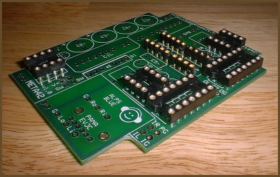
Virtually every hole in the board is on 0.100" spacing relative to all the related holes. Also, each resistor's holes are 0.300" apart. This means you can use DIP IC sockets, SIP socket strips and SIP header pin strips in the board. If you did this for everything where it makes sense, you would in effect have a META42 breadboard for maximum tweakability. :) Here's a list of all the places you can do this and ideas for why you might want to do each one:
- Resistor/diode blocks — Use DIP-14 sockets or
socket strips to allow easy swapping of resistors and diodes.
- Input and outputs — Solder SIP pins in the holes,
and crimp or solder female terminals (e.g. Digi-Key WM2600) onto
the ends of the hookup wires to allow easy disconnection of the
panel jacks. This might be useful for disassembling your amplifier
for servicing without removing the jacks from the panels —
just disconnect the jacks from the board, lift the board out, and
the panel components can stay in place.
- Power pins — Similar to above, but the foursquare configuration allows you to use commonly-available 2x2 connectors. Or, you could use a 2x3 connector and also run the power switch in the same wiring harness.
|
A META42 v1 "Breadboard"
Stacking Buffers
The EL2001 buffer is stackable. This means you can literally stack them on top of each other and solder their pins together to run multiple buffers in parallel. This makes the amp sound better, for a number of reasons:
- It improves the slew rate of the buffers, which lowers
distortion. See the load vs. slew rate graph(s) in the buffer's
datasheet. With stacked buffers, the load is divided among the
buffers. Treble response benefits the most from this.
- It increases the transient output ability of the amp. While
your headphones probably don't need more continuous current than
one buffer can supply, additional buffers can help deal with the
peak load, which may indeed tax a single buffer's capability. Bass
response benefits the most from this.
- It lowers the output impedance of the amplifer. Most headphones sound best when the amplifier's output impedance is as close to 0 as possible.
You don't need to stack buffers to get good sound. It's a "last 10%" tweaking kind of thing.
As far as I can tell, you need to double the number of buffers each time to get a noticeable improvement, and with each additional level of buffers the improvement diminishes. Adding a second buffer to each channel gives a small but noticeable improvement. Doubling that to four per channel is a bit "out there" in terms of bang for the buck. I haven't tried going beyond 4 per channel yet, but I suspect it would amount to a pretty tiny improvement.
You might think stacking power supply buffers would help. After all, the benefits mentioned above should help the virtual ground as well, since this is where the amp's output currents return. For reasons I don't yet understand, though, stacked ground buffers don't seem to help much, if at all.
Removing the Buffers
Just as you can add buffers to optimize the amp by spending more money, you can save money by removing the buffers. All three buffers are technically "optional". Just jumper pin 2 to pin 7.
If you remove the output buffers, the op-amp chip will have to be strong enough to drive the load all by itself. Even if the chip is capable of a farily high output current, it won't sound as good as when it's insulated from the load by a buffer. Also, the multiloop and global feedback configurations won't work without a buffer. You can only use the local feedback configuration if you remove the output buffers.
If you remove the power supply buffer, the power rails will only remain stable up to about 20mA. Once the circuit begins drawing more than this, the rails will become unbalanced. I have a short discussion in another article that goes into the problems caused by unbalanced power rails, and why it's worth fixing these problems.
EL2001 vs. EL2002
NOTE: This section is mostly obsolete now that the last of the EL2002s I had for sale are gone. You may yet be able to find a few of them at surplus dealers, but for all intents and purposes, this buffer is no longer available.
We now return you to our regularly-scheduled discourse.
—
The standard buffer for the META42 is the EL2001CN, but there's a related part called the EL2002CN. This part is the same basic circuit as the EL2001 internally, except that it's set up for higher bandwidth: 180 MHz vs. the EL2001's 70 MHz. The downside is that the buffer has a higher quiescent current draw: 5 mA per buffer vs. the EL2001's 1.5 mA. This makes the EL2002 a poor choice for battery-powered amps; you could instead stack two EL2001s on each channel and also add current sources and still have a lower current draw than going with single EL2002s.
The higher speed of the EL2002 does mean somewhat better sound, but in my experience the sonic difference between these buffers is fairly small. Indeed, I'd say that a pair of stacked EL2001s sounds better than a single EL2002. The best reason to use EL2002s is if you're doing a wall-powered amp and want the best possible sound from this amp, without going to nonstandard parts. There's also some concern with the bandwidth of the op-amp, in that a fast op-amp with a slower buffer can be unstable, but the solution to that in the META42 is to just raise the inner loop gain until the amp is stable again. Even this isn't a big concern, since most people use op-amps that are much slower than 70 MHz, so the EL2001 is the right buffer most of the time for this reason, too.
Biasing the Op-Amp into Class A
"Class A" refers to configuring an amplifier so that its output devices remain turned on all the time. This reduces thermal variation and eliminates crossover distortion, which makes the amp sound better.
The recommended method for biasing a META42's op-amp into class A is called the "JFET cascode", which are Q1 and Q2 on the META42 board. These transistors have to be chosen in a particular way to ensure that the cascode behaves properly; you can read my op-amp biasing article to learn how to find workable pairs yourself, or you can order tested transistor sets with the META42 board. The article also explains how the cascode works, and also talks about several other methods for biasing op-amps into class A, most of which are directly supported by the META42 board.
I recommend that you wait to bias the op-amp until you've got the amp working without it. It's no more difficult to add it later. If the amp doesn't work at first, it will be easier to find the problem if you don't have to chase biasing problems at the same time. For battery-powered amps, you may choose to leave it out because the amp sounds good enough to you without the bias. For wall-powered amps, the extra current draw isn't going to matter, but some op-amps don't benefit from biasing, so you might still choose to leave it out.
Adding Crossfeed
This is explained in a separate article.
This space intentionally left blank. :)