Step-by-Step Assembly Guide
This assembly guide assumes that you've built amps before and that you just need guidance on the decisions you will have to make while assembling this particular amplifier. See the FAQ for my stance on what experience level you need to build this amplifier.
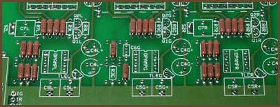
1. Add most resistors and D1
|
If you want a PPA breadboard, add the sockets now.
Add all the resistors, except for R7, R9 and the LED resistor. We will add these later.
Add D1, the power protection diode. Although this diode is technically optional, I recommend that you always put it in, no matter what your power configuration is.
2. Jumper S2
If you will be adding bass boost later, use a wire loop large enough that you can easily remove it later. Otherwise, make the jumper nice and short.
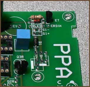
3. Configure the power indicator LED
Assuming you want a power LED, you have several choices here. From simplest to most complicated:
The first option is best for wall-powered amplifiers. If you use it with a battery-powered amp, the LED will change in brightness as the battery pack is drained.
The other options are best for battery-powered amplifiers. They keep the LED at a constant brightness until the batteries get low, and then they turn the LED off to warn you that the amp needs recharging.
If you have a battery-powered amp and want constant LED brightness but you don't want the LED to turn off, you can use the second or third options but with ZNR jumpered.
I wouldn't recommend that you add the LED just yet. You'll want to wait until you get near to doing the casework.
4. Configure the power rails
|
The default power rail configuration is to use 6 or 12 Q3s and all three TLEs. Install all of these parts now.
There are a few alternate power configurations you may want to consider, if you're a tweaker.
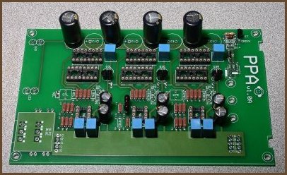
5. Add the capacitors and sockets
|
Now that all of the small components are placed, you can start placing the large ones. Notice that the electrolytic capacitors (C1 and C4) are polarized: the long lead must go into the hole with the square pad. The remaining caps can be placed in the holes in any orientation.
Leave the C7s out even if you know you will want them eventually.
6. Test the power supply
If you're going to wire the power supply directly to the PPA board, solder the wires to the board and strip the ends. Then you can either temporarily solder a DC power jack to the wires, or use alligator clips to connect your power supply to the wires.
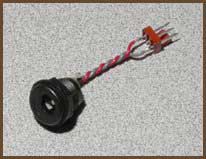
If you're taking advantage of the Molex KK support, there are two ways to go. Either put a male connector directly on the board, or put a female on the end of wires going back to the PPA's power pads. I recommend the latter when using the battery board. Then, make an adapter with the mating Molex connector and a DC power jack, like this:
|
(Incidentally, the B+ connection isn't involved with this test. You can hook it up right now or leave it for later, whichever makes you happy.)
You will need to jumper across the S1 pads as well. Instead of using simple jumpers, it's better to put wires long enough to reach your power switch into the pads and solder their ends together temporarily.
You may want to add the LED at this stage.
Power the board up and measure from the virtual ground plane to the power pads at the op-amp sockets, and at one buffer socket in each group. The voltage magnitudes should be nearly equal, and the LED should be lighting up if you added it. If not, you have a problem in the amp you'll need to fix before proceeding.
When you're satisfied that the chips are receiving the proper voltages, turn off the power.
7. Do the panels
Set the amp board aside and put the holes in the panels for the components you want. Here are some typical arrangements for the Hammond 1455N16 panels: Standard panels, v1.0 (PDF, 55K)
You can either mount the components to the panels now, or you can add them one by one later as you wire each one up.
8. Mount the board in the case
If you're using a case like the Hammond 1455N16 where the board slides into rails in the side of the case, the critical issue is the pot, since it must align with the hole you drilled in the panel. Insert the pot's lugs into the board, slide the board in the case so the solder side faces the removable panel, and attach the front panel. Align the pot so the shaft is square with the panel and the bushing is centered within the hole, then solder the pot to the board. If you will be mounting the board in the case with the solder side away from the removable panel, it should still be aligned relative to the panel since there's only 4 mils of difference between the two arrangements.
If you're using some other kind of case, you will probably be mounting the board to the bottom of the case. The mounting holes in the corners of the board are on the corners of a 3.6" × 6" rectangle. The holes are sized to accept #4 American or M3 metric machine screws.
|
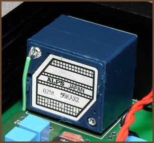
If you use an ALPS RK27, you should add a ground strap to one of the ground pads on the board, as shown in the picture. If you're using some other pot, you may or may not need to ground the case like this. If you get a buzzing or humming sound in the headphones when you touch the shaft of the pot, try adding a ground strap.
9. Wire up a basic set of panel components
Next, add the wires for one signal input, one output, power input and a power switch. If your amp will have extra features like multiple I/O jacks, crossfeed, or bass boost, you don't want to hook them up just yet because they add complexity which will make troubleshooting more difficult if something isn't working right.
You can mount the power LED to the panel at this point, if you want to.
IL, IR, IG
These are the input pads: left, right and ground. They are positioned to be near the input jacks on the rear panel of your amp's case, so the wires to them can be very short. However, be sure to leave enough slack that you can pull the amp board out the front side of the case; you need to be able to swing the rear panel out and up to do this. If you don't have enough slack, you have to remove the front panel to remove the PPA board from the case, which is tougher than removing the rear panel.
If you will be adding crossfeed, make the wires long enough that you can cut them in half to put the crossfeed board inline.
OL, OR, OG
These are the output pads. Be careful running the wires from these to the output jack, since the wires will be rather long. Consider twisting the wires together and running the bundle well above the board to minimize crosstalk and noise pickup.
|
V+, V-, B+
These are the power supply pads. Notice that there are two overlapping Molex KK connector arrangements at a right angle to each other plus a third complete set of power pads. This accommodates many purposes.
If you're using wall power only, simply run the wires from the DC input jack to whichever V+ and V- pads are convenient. You can use a Molex KK connector here if you want, but I'd only do that if you also have the audio input wires going to a similar connector. This would let you remove the rear panel from the board, if you needed to disassemble the amp for servicing.
If you're using a battery board as well as wall power, there are a couple of ways you can arrange things. The way I like to do it is to run wires from the DC input jack to one set of V+/V- pads, and then run wires from another V+/V-/B+ set down to a Molex connector on the battery board. Instead, you could put the Molex on the PPA board, but that's a tall component near the rear panel, which may get in the way. Don't be tempted to wire the two boards directly together, because it's trickier to slide the two boards in and out at the same time, and it's easier to work on the boards separately if that is ever necessary.
S1+, S1-
These are for your power switch. If you have a single-voltage power supply, you can jumper across S1- if you only want to use a single-pole power switch. There may be some failure modes where cutting both power lines will help even with a single-voltage supply. If you are using a dual-voltage supply, you must use a dual-pole power switch here.
S2
S2 is the bass boost switch, a DPST type. (Or a DPDT type with one set of throw lugs ignored.) It should be jumpered until you're sure the amp is working without bass boost.
10. Add the chips and test the amp
Put the op-amps in, and add one buffer per channel. With no source and no headphones plugged in, turn the amp on and let it sit for a bit. Then, touch the tops of the chips to see if they are getting warm. The buffers will get a bit warm to the touch, but they shouldn't be hot. The op-amps should be cool.
Then, take your meter and put it on the DC millivolts setting and measure from the ground plane to the output of each of the three channels; you should only be getting a few millivolts at most. If you are getting a few tens of millivolts, that's still okay, but you can't safely add the bass boost; you'll need to find out what's causing this offset and fix it before adding bass boost because it will exacerbate the problem. If you're getting more than a few tens of millivolts, you'll need to fix the problem regardless, as excessive DC offset will damage headphones.
Once the amp appears to be operating correctly, turn the volume all the way down, plug the source into the amp, plug some cheap headphones into the amp, and start something playing. Leave the headphones on the table, and slowly turn up the volume. If the volume shoots up quickly or you get ugly noises (buzzes, squeals, crackles), you've probably got some kind of oscillation going on. (Aren't you glad the headphones aren't on your ears now?) Turn the amp off and unplug the headphones, then find out what the problem is before continuing. Don't just unplug the headphones! You can damage the buffers that way.
Once the volume is ramping up and down nicely as you turn the volume knob, put the headphones on and listen critically. Ramp the volume up and down gently. Then turn the knob back down and try the amp with your good headphones, repeating these tests.
11. Add the op-amp biasing cascodes (optional)
Now that the amp is working, you may wish to bias the op-amps into class A. This is strictly optional. I recommend that you do not do this tweak until you are certain that the amp is working well. If your amp has problems, it will be simpler to pinpoint the source of the problem if your amp's configuration is as simple as possible.
12. Add bass boost (optional)
If you want to play with bass boost, you can add it now.
First, add R7 and C7. I recommend starting with 10 kΩ for R7 and 0.1 µF for C7. The +3dB point with these values is about 200Hz, and it only boosts 6dB total. I like to leave a bit of space under the R7s to make them easier to remove if I need different values for some reason.
Next, desolder the jumpers you put into S2 previously and put a switch here so that S2 is open when you want bass boost and closed when you want flat frequency response. The wires from S2 to the front panel will be rather long and the signal level at S2 is very low and delicate. You want to be very careful with the wires you run from these positions to the switch or else you can introduce audible problems into the circuit through these long wires.
Check the DC offset at the output of the amp with bass boost engaged before plugging your headphones in. If the offset is more than a few tens of millivolts, you either need to find out how to fix the offset, or you'll have to lower the amount of bass boost since this amplifies DC offsets as well as the bass line.
13. Add crossfeed (optional)
The PPA has mounting holes for my crossfeed PCB. You simply connect wires from the amp's input jacks to the 'I' pads on the crossfeed board, and wires from the 'O' pads to the 'I' pads on the PPA.