Project History and Acknowledgements
The META42 is based on a lot of ideas advocated by Phillip P. LaRocco, a.k.a. ppl, yet he had relatively little to do with the actual work on the META42 circuit board. Over time, the people who worked closely with the META42 began learning more more about what ppl had been doing in his own amps. We found that there were many interesting features in these amps not present in the META42, and so in the Fall of 2002 morsel talked ppl and I (tangent) into joining with her to create a more advanced circuit and PCB based on these improved circuit ideas.
The PPA has a lot in common with the predecessor amps ppl has built, but it’s not a clone of any of them. Instead, we started from a fixed board size and then started seeing what we could fit into that space. For a while, we considered using a smaller board that would fit Hammond’s 1455K16 or K12 series cases, but it quickly became obvious we’d want more space than that. Even with the larger boards that the N16 case will hold, we’ve still got features we had to let go because we weren’t able to cram them onto the board.
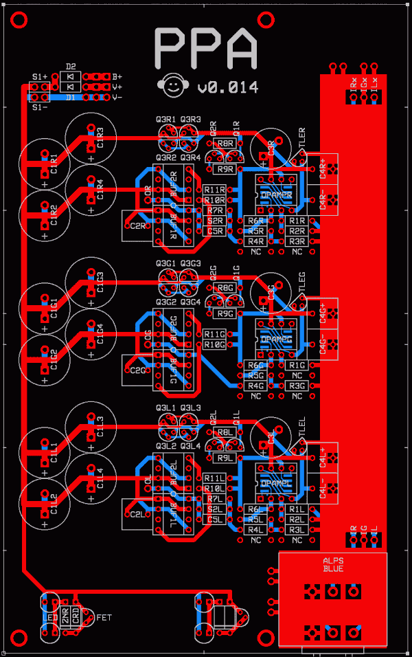
Here’s the first board version we showed to the public back in March of 2003 in the project announcement thread on Head-Fi:
|
The public’s first peek at the PPA, v0.014
v0.014 is very similar to our first prototype, v0.012, which was good but imperfect. Between the problems we discovered on our own and some comments from the first public showings, we made several changes, culminating in our second prototype, v0.023 in late April 2003. More people heard that version, including several people outside the Team at two different Head-Fi meets, where the amp was received well.
Over the next few months, we iterated on the design some more, finally arriving at v0.034 in late July. This was tested and released without changes as version 1.0 a month later.
|
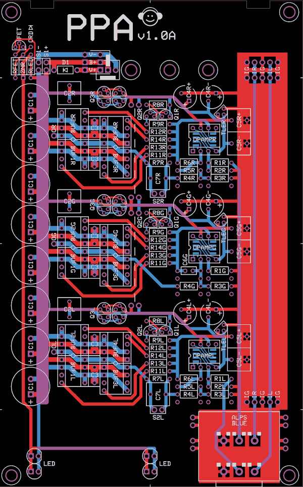
Version 1.0A, released August 2003
After some months of experience with PPA 1.0, ideas on how to improve the design started to accumulate. Without changing the board size or straying from the design principles that led to v1.0, we made several incremental improvements, resulting in v1.1:
|
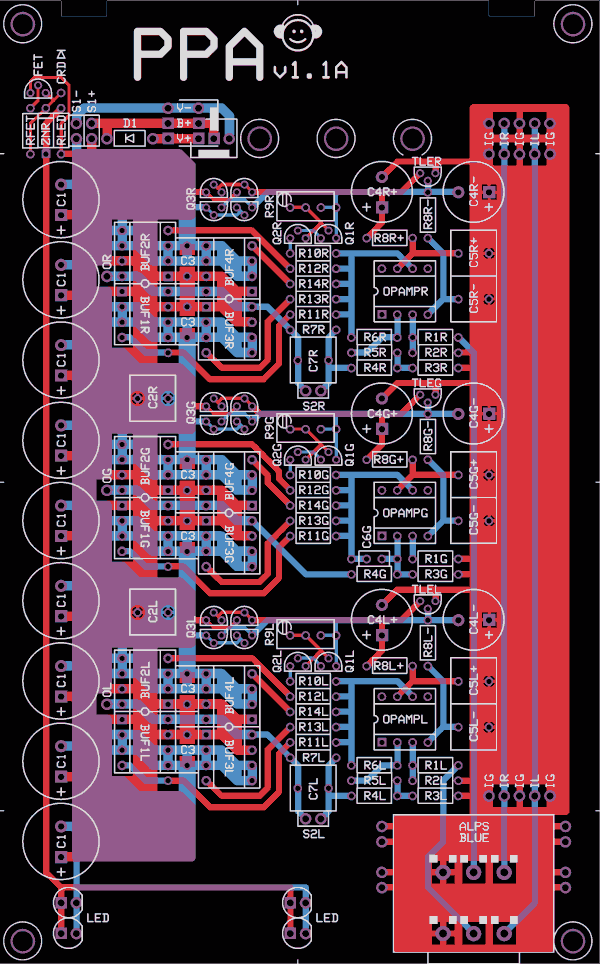
Version 1.1A, released May 2004
Throughout the 1.x period, various discrete transistor buffer add-on modules were created to replace the standard monolithic buffers. For version 2.0, we added our own diamond buffer to the board, plus a few other changes:
|
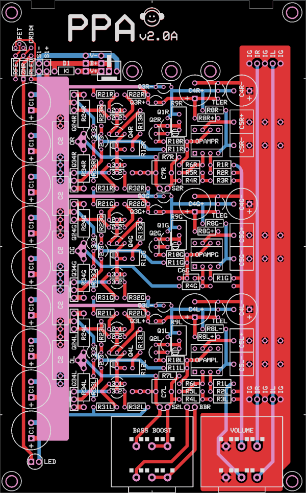
Version 2.0A, released March 2005
Released Board Version History
v2.0B, C, D...: Just later board runs
v2.0A:
- Replaced 4× HA-5002 monolithic buffers with discrete transistor diamond buffer designed by ppl.
- More room set aside for bass boost caps, allowing higher-quality types to be used.
- Some capacitor mounting holes are slightly larger.
- Additional set of output pads, for nonstandard wiring setups.
- Added board-mounted pot for adjustable bass boost.
- Removed center LED pads to enable previous feature.
- C2s now favor long, skinny caps. (Axial caps ideal.)
- R3G still present, but unlabeled on PCB.
- All TO-92 parts use splayed-leg layouts instead of triangular layouts.
- Many small layout tweaks to “unchanged” circuitry to allow above changes.
v1.1A:
- Op-amp class A bias current is now adjustable. (R9, previously R8.)
- Changed the C2 inter-channel bypass arrangement.
- Increased the extent of the power rail copper plane around the buffers.
- Added a ninth C1, for users of larger than normal cases.
- Added R8, which forms an RC low-pass filter with C4||C5 to reduce HF noise on the op-amp rails, increasing stability.
- C4 enlarged to allow 10mm diameter caps.
- Removed the no-connect pads that allowed putting resistors in DIP-8 sockets, to make room for the previous two features.
- Removed the SO-8 pads for the op-amps.
- Removed the rail tie pads.
- Fixed a compatibility problem with the HA-5033/OPA-633 alternate buffer.
v1.0C: C4 holes slightly larger to accommodate certain audiophile caps.
v1.0B: Small change to rail tie pads.
v1.0A: First release.
Why Is It Called “PPA”?
ppl has previously hand-built several amps in this rough size range of varying levels of complexity, and he called them “pocket amps” or “portable amps.” Since the META42 name made no mention of ppl despite our debt to his pioneering work, we decided to call this PPL’s Portable Amplifier to redress the balance.
Who Did What
ppl pioneered most of the core design ideas for headphone amp use, including Jung multiloop topology, the use of JFETs for isolating the high and low-current power rails, JFET cascodes for biasing op-amps into class A, the bass boost filter, and the low-battery LED cutoff circuit. He also designed the diamond buffer used in PPAv2.
morsel brought ppl and I together to
start the project, did most of the amp board layout work, and acted as
slave driver...er, project coordinator.
morsel and ppl collaborated on the differential drive design.
KurtW did a lot of testing on the second prototype.
I (tangent) have done lots of testing, lots of parts compatibility checking, and the occasional small bit of layout. I also did the battery board and the changes necessary to make my crossfeed PCB work with the PPA.