Step-by-Step Assembly Guide
This assembly guide assumes that you’ve built amps before and that you just need guidance on the decisions you will have to make while assembling this particular amplifier. See the FAQ for my stance on what experience level you need to build this amplifier.
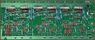
1. Add most resistors and D1
|
If you want a PPA breadboard, add the sockets now.
Add all the resistors, except for R7, R9, R12 and the LED resistor. We will add these later.
Add D1, the power protection diode. Although this diode is technically optional, I recommend that you always put it in, no matter what your power configuration is.
2. Jumper S2
If you will be adding bass boost later, use a wire loop large enough that you can easily remove it later. Otherwise, make the jumper nice and short.
3. Configure the power indicator LED
Assuming you want a power LED, you have several choices here. From simplest to most complicated:
The first option is best for wall-powered amplifiers. If you use it with a battery-powered amp, the LED will change in brightness as the battery pack is drained.
The other options are best for battery-powered amplifiers. They keep the LED at a constant brightness until the batteries get low, and then they turn the LED off to warn you that the amp needs recharging.
If you have a battery-powered amp and want constant LED brightness but you don’t want the LED to turn off, you can use the second or third options but with ZNR jumpered.
I wouldn’t recommend that you add the LED just yet. You’ll want to wait until you get near to doing the casework.
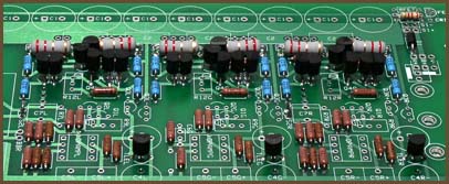
4. Install the mandatory TO-92 parts
|
Install the 6 Q3s, the 3 Q4s, the 18 small buffer transistors (Q21-Q33), and all three TLEs.
If you want to match the buffer driver transistors with an hFE meter, the pinout of the transistors are EBC with the pins downward and looking at the flat face of the transistor.
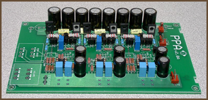
5. Add the big stuff
|
Now that all of the small components are placed, you can start placing the large ones.
Add all the capacitors except C7, even if you know you will want it eventually. Notice that the electrolytic capacitors (C1 and C4) are polarized: the long lead must go into the hole with the square pad. The remaining caps can be placed in the holes in any orientation.
Add the sockets, the R12s, and the output transistors.
If you want to match the output transistors with an hFE meter, the pinout of the transistors are ECB with the pins downward and looking at the label (non-metal) side of the transistor.
6. Test the power supply
If you’re going to wire the power supply directly to the PPA board, solder the wires to the board and strip the ends. Then you can either temporarily solder a DC power jack to the wires, or use alligator clips to connect your power supply to the wires.
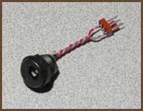
If you’re taking advantage of the Molex KK support, there are two ways to go. Either put a male connector directly on the board, or put a female on the end of wires going back to the PPA’s power pads. I recommend the latter when using the battery board. Then, make an adapter with the mating Molex connector and a DC power jack, like this:
|
(Incidentally, the B+ connection isn’t involved with this test. You can hook it up right now or leave it for later, whichever makes you happy.)
You will need to jumper across the S1 pads as well. Instead of using simple jumpers, it’s better to put wires long enough to reach your power switch into the pads and solder their ends together temporarily.
You may want to add the LED at this stage.
Power the board up and measure from the virtual ground plane to the power pads at the op-amp sockets. The voltage magnitudes should be nearly equal, and the LED should be lighting up if you added it. If not, you have a problem in the amp you’ll need to fix before proceeding.
7. Test the amp, part 1
With no source and no headphones plugged in, install the op-amps, turn the amp on and let it sit for a bit.
Then, touch the tops of the op-amps to see if they are getting warm. They should be just slightly warmer than when powered off. You might not be able to feel any additional warmth at all with some chips.
Do the same for the buffer transistors, except that you are testing for truly hot parts, not merely warm. It’s best to use the back of your finger here, rather than your finger tip, in case they are too hot. If you can’t leave your finger on the transistors for more than a few seconds, be concerned. If you are immediately burned, something’s definitely wrong.
If you found any problems with the preceding tests, follow the instructions in Basic Troubleshooting for Headphone Amplifiers.
8. Adjust the buffer bias
The default bias for the PPA’s output stage is 20 mA. If you are using the default 2.2 Ω output resistors, this will force 44 mV across each output resistor.
To make this adjustment, power up the amp and adjust the bias trimmer until you get the proper DC voltage drop across one of the output resistors in that channel. There’s no need to measure both; the voltage drop will be the same either way. Just pick the most accessible one.
It’s possible to hold your meter’s probes across the output resistor with one hand while trimming the bias point with the other, but be careful not to slip and short something out! Several people (including myself) have destroyed PPA output buffers that way. If you have small test clips, it’s best to run clips from the resistor leads out to your meter’s probes before turning the amp on to prevent this problem. Alternately, you can make a small adjustment of the pot, put your trimming scredriver down, take a careful measurement using both hands, then tweak again, repeating until you dial it in.
Repeat this process for the other two channels.
Distortion goes down as the bias current goes up, but higher bias also raises the amp’s current draw and heat output. The lowest bias point we had any regular success with during the design stage is 10 mA; this is low enough for battery use, and still gives quite good test results. (See the benchmarks.) In testing, we took it as high as 40 mA, at which point there was clearly no more improvement to be had. Personally, I think 30 mA is the highest practical bias point.
9. Do the panels
Set the amp board aside and put the holes in the panels for the components you want. Here are some typical arrangements for the Hammond 1455N16 panels: Standard panels, v2.0 (PDF, 68 KB)
The diagrams in that document are 1:1 scale, so the idea is to print the pages for the layouts you’re interested in, cut them out, and use them as punch and drill guides. Some printers may scale the layouts down slightly, but this can usually be fixed by digging around in the printer’s options. Your PDF reader may also have some program-specific options that will help with scaling problems.
You can either mount the components to the panels now, or you can add them one by one later as you wire each one up.
10. Mount the board in the case
If you’re using a case like the Hammond 1455N16 where the board slides into rails in the side of the case, the critical issue is the pot, since it must align with the hole you drilled in the panel. Insert the pot’s lugs into the board, slide the board in the case so the solder side faces the removable panel, and attach the front panel. Align the pot so the shaft is square with the panel and the bushing is centered within the hole, then solder the pot to the board. If you will be mounting the board in the case with the solder side away from the removable panel, it should still be aligned relative to the panel since there’s only 4 mils of difference between the two arrangements. (That’s about the thickness of a standard piece of paper.)
If you’re using some other kind of case, you will probably be mounting the board to the bottom of the case. The mounting holes in the corners of the board are on the corners of a 3.6" × 6" rectangle. The holes are sized to accept #4 American or M3 metric machine screws.
|
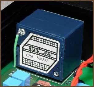
If you use an ALPS RK27, you should add a ground strap to one of the ground pads on the board, as shown in the picture. If you’re using some other pot, you may or may not need to ground the case like this. If you get a buzzing or humming sound in the headphones when you touch the shaft of the pot, try adding a ground strap.
11. Wire up a basic set of panel components
Next, add the wires for one signal input, one output, power input and a power switch. If your amp will have extra features like multiple I/O jacks, crossfeed, or bass boost, you don’t want to hook them up just yet because they add complexity which will make troubleshooting more difficult if something isn’t working right.
You can mount the power LED to the panel at this point, if you want to.
IL, IR, IG
These are the input pads: left, right and ground. They are positioned to be near the input jacks on the rear panel of your amp’s case, so the wires to them can be very short. However, be sure to leave enough slack that you can pull the amp board out the front side of the case; you need to be able to swing the rear panel out and up to do this. If you don’t have enough slack, you have to remove the front panel to remove the PPA board from the case, which is tougher than removing the rear panel.
If you will be adding crossfeed, make the wires long enough that you can cut them in half to put the crossfeed board inline.
OL, OR, OG
These are the output pads. Be careful running the wires from these to the output jack, since the wires will be rather long. Consider twisting the wires together and running the bundle well above the board to minimize crosstalk and noise pickup.
V+, V-, B+
These are the power supply pads. Notice that there are two overlapping Molex KK connector arrangements at a right angle to each other plus a third complete set of power pads. This accommodates many purposes.
If you’re using wall power only, simply run the wires from the DC input jack to whichever V+ and V- pads are convenient. You can use a Molex KK connector here if you want, but I’d only do that if you also have the audio input wires going to a similar connector. This would let you remove the rear panel from the board, if you needed to disassemble the amp for servicing.
If you’re using a battery board as well as wall power, there are a couple of ways you can arrange things. The way I like to do it is to run wires from the DC input jack to one set of V+/V- pads, and then run wires from another V+/V-/B+ set down to a Molex connector on the battery board. Instead, you could put the Molex on the PPA board, but that’s a tall component near the rear panel, which may get in the way. Don’t be tempted to wire the two boards directly together, because it’s trickier to slide the two boards in and out at the same time, and it’s easier to work on the boards separately if that is ever necessary.
S1+, S1-
These are for your power switch. If you have a single-voltage power supply, you can jumper across S1- if you only want to use a single-pole power switch. There may be some failure modes where cutting both power lines will help even with a single-voltage supply. If you are using a dual-voltage supply, you must use a dual-pole power switch here.
S2
S2 is the bass boost switch, a DPST type. (Or a DPDT type with one set of throw lugs ignored.) It should be jumpered until you’re sure the amp is working without bass boost.
12. Test the amp, part 2
With the board mounted in the case and no source or headphones plugged in, turn the amp on and re-do the heat tests to make sure nothing has changed.
If all the active parts’ temperatures are reasonable, take your meter and put it on the DC millivolts setting and measure from the ground plane to the output of each of the three channels. You should only be getting a few millivolts at most. If you are getting a few tens of millivolts, that’s still tolerable, but you can’t safely add the bass boost; you’ll need to find out what’s causing this offset and fix it before adding bass boost because it will exacerbate the problem. If you’re getting more than a few tens of millivolts, you’ll need to fix the problem regardless, as excessive DC offset will damage headphones.
Again, follow the instructions in Basic Troubleshooting for Headphone Amplifiers if you encounter any worrying symptoms.
With those preliminary tests out of the way, turn the volume all the way down, plug the source into the amp, plug some cheap headphones into the amp, and start something playing. Leave the headphones on the table, and slowly turn up the volume. If the volume shoots up quickly or you get ugly noises (buzzes, squeals, crackles), you’ve probably got some kind of oscillation going on. (Aren’t you glad the headphones aren’t on your ears now?) Turn the amp off and find out what the problem is before continuing.
Once the volume is ramping up and down nicely as you turn the volume knob, put the headphones on and listen critically. Ramp the volume up and down gently. Then turn the knob back down and try the amp with your good headphones, repeating these tests.
13. Add the op-amp biasing cascodes (optional)
Now that the amp is working, you may wish to bias the op-amps into class A. This is strictly optional. I recommend that you do not do this tweak until you are certain that the amp is working well. If your amp has problems, it will be simpler to pinpoint the source of the problem if your amp’s configuration is as simple as possible.
14. Add bass boost (optional)
If you want to play with bass boost, you can add it now. There are two major ways to set up bass boost: the old PPAv1 way, with a switch for bass boost and a fixed boost level, or the new PPAv2 way, with adjustable boost.
PPAv2 Adjustable Boost
Add the bass boost pot and C7. I recommend starting with 0.1 µF for C7. The same 50 kΩ unit you use for volume will work just fine for the bass boost pot.
Next, desolder the jumpers you put into S2 previously. This will allow the boost adjust pot to do its job.
Finally, you need to run two wires from the pads marked BBR to the R7R pads. The left channel is already wired like this on the board. Layout constraints prevented us from pre-wiring the right channel the same way.
PPAv1 Switchable Boost
First, add R7 and C7. I recommend starting with 10 kΩ for R7 and 0.1 µF for C7. I like to leave a bit of space under the R7s to make them easier to remove if I need different values for some reason.
Next, desolder the jumpers you put into S2 previously and put a switch here so that S2 is open when you want bass boost and closed when you want flat frequency response. The wires from S2 to the front panel will be rather long and the signal level at S2 is very low and delicate. You want to be very careful with the wires you run from these positions to the switch or else you can introduce audible problems into the circuit through these long wires.
Tests (same for both variants)
Turn bass boost off. With the PPAv2 adjustable boost, this means turning the boost pot all the way counterclockwise. Then, check the DC offset at the output of the amp: it should be the same as when you did the earlier DC offset test. Then, turn bass boost fully on. Re-test DC offset: it will have risen, so the question is whether it has risen too high. Again, be worried if it is more than a few tens of millivolts.
Once you’re satisfied with the DC offset test, plug your headphones in, turn on some music, and play with the boost. Now you can start evaluating whether you need to change the boost cap value, or in the case of the PPAv1 switchable boost, the boost adjust resistor. See the bass boost section for advice on choosing different part values.
15. Add crossfeed (optional)
The PPA has mounting holes for my crossfeed PCB. You simply connect wires from the amp’s input jacks to the “I” pads on the crossfeed board, and wires from the “O” pads to the “I” pads on the PPA.